سبد خرید شما خالی است!
تستر قطعات الکترونیکی LCR T4
- کد محصول: LCRT4
- امتیاز جایزه: 100
- موجودی: در انبار
توضیحات کوتاه
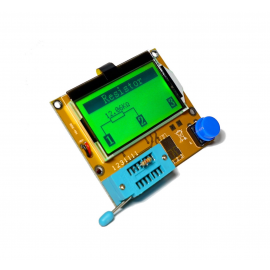
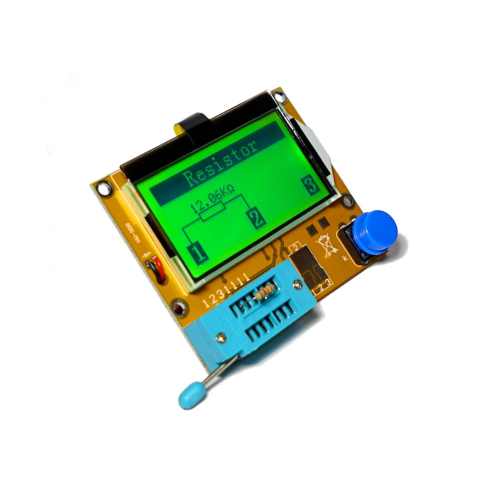
محصول پیش رو یک تستر گرافیکی همه فن حریف میباشد که کاربرد فراوانی برای علاقمندان به الکترونیک دارد شما میتوانید توسط دستگاه زیر انواع مقادیر مقاومت, خازن , سلف , دیود, ماسفت و بسیاری از قطعات را اندازه گیری نمایید . همچنین محصول فوق برای تشخیص نوع...تستر قطعات الکترونیکی LCR T4
محصول پیش رو یک تستر گرافیکی همه فن حریف میباشد که کاربرد فراوانی برای علاقمندان به الکترونیک دارد شما میتوانید توسط دستگاه زیر انواع مقادیر مقاومت, خازن , سلف , دیود, ماسفت و بسیاری از قطعات را اندازه گیری نمایید . همچنین محصول فوق برای تشخیص نوع ترانزیستور ها و نوع دیودها و ... کاربرد بسیاری دارد.
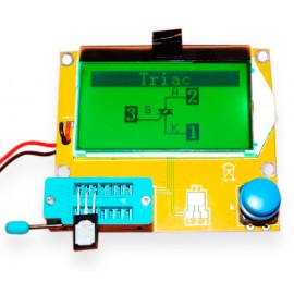
همچنین این دستگاه قابلیت اندازه گیری ظرفیت و ولتاژ خازن ها و ... را دارا میباشد . توسط این دستگاه با توجه به ترسیم دیاگرام مداری میتوانید براحتی پایه ها ترانزیستورها و دیودها و ... را براحتی تشخیص و مشاهده کنید و میزان مقاومت داخلی قطعاتی نظیر سلف و ... را برای شما محاسبه خواهد نمود .
محصول پیش رو یک محاسبه گر پیشرفته بوده و به نوعی میتوانید از آن در حل محاسبات مداری و سری و موازی کردن مقاومت ها و ... استفاده برده و لذت ببرید.
منبع تغذیه این دستگاه یک عدد باتری 9 ولتی کتابی بوده و همچنین نمایشگر آن دراری بک لایت برای مشاهده آسان شما در شب و روز میباشد .
مشخصات فنی محصول به شرح زیر میباشد:
Main Function:(New add function: Boot automatic detection function)
1. One key to boot, one key test, automatic recognition device type, automatic switching range, automatically shut down after the test.
2. Shutdown standby current minimum is only 20na, ultra long standby, the standby power consumption can be ignored, and can be used in battery powered.
3. Automatic detecting the PNP and NPN type bipolar transistor, N, P channel MOSEFT, JEFT, two level pipe, dual two stage tube, thyristor SCR (SCR), three
tubes, resistors, capacitors (electric discharge must be done first before measurement of capacitance), the capacitance ESR value
4. Automatic detect pin layout and given a label according to the actual sequence.
5. The threshold voltage and current measurement of bipolar transistor amplifying coefficient and the emitter junction leakage current, ICE.
6 Darlington transistor can be through the high threshold voltage and high current amplification factor identification.
7. The bipolar transistor, MOSFET protection and detection two tubes and the forward voltage drop Uf.
8. To detect threshold voltage VT of MOSFET and measure the gate capacitance value C.
9. Detection and transistor and MOSFET protection class two tube magnification and the determination of the base data, to confirm emitter transistor the forward voltage
10. Support two resistance measurement at same time and symbol display, a maximum of four digit display. The display of resistance symbol two end is the tester probe number connection (1-3). So the adjustable potentiometer can also be measured (if the potentiometer to adjust to its end, the tester can not distinguish the middle and both ends of the pin)
11. The resistance measurement resolution is 0.1 ohms, the highest measurement value is 50M ohms.
12. The highest four digit display-capacitor capacitance value range from 25pf (clock 8M Hz clock, 50pf@1MHz) to 100mF. The resolution can reach 1pF (@8MHz clock).
13 Measure the capacitance the capacitor equivalent series resistance of the 2UF numerical above (ESR) ,the resolution is 0.01 ohms and display two digit numerical.
14. Display right direction signs of two two level , and display the forward voltage drop.
15. LED detection is two level pipe, flashes continuously several times during the testing, double emitting two tubes detected as the double diode.
16. It can test the zener diode, if the reverse breakdown voltage is lower than 4.5V it shows two pieces diodes, and it can be confirmed by the voltage. The probe around the diode symbol is the same,in this case, you can identify the diode true anode by the threshold voltage at 700mV more or less!
17.It can measure the single diode reverse capacitance values. Bipolar transistor also can be measured, and then must be connected with the base and collector or emitter.
18.The connection of the whole bridgerequires can be measured only one time.
19. The maximum of capacitor test is 1000000uf, the best testing range is 0.2nF~7000uF, if the test value is below the 25pf capacitor, and a diode in parallel manner or at least 25pf shunt capacitor. After get the measured results, then use it to minus parallel capacitor solute.
20. The inductance test range: 0.01mH~20H, more than 20H, less than 2100 ohm resistance could be identified as inductance, the measurement results show only a single inductor, and display the inductance value.
21. The test time is about two seconds, large capacitance and inductance measurement time will be extended as the actual value.
22. Automatic shutdown, after the test it has been show test results about 3 seconds, then shut down.
23. It can be extended fixture after testing device, this fixture needs self DIY or purchase it.
محصولات مرتبط
ست پیچ گوشتی کروم وانادیوم Kaisi KS-3801
یک ست پیچ گوشتی بسیار حرفه ای همراه با سری های مختلف - پنس و سایر ابزارها..

